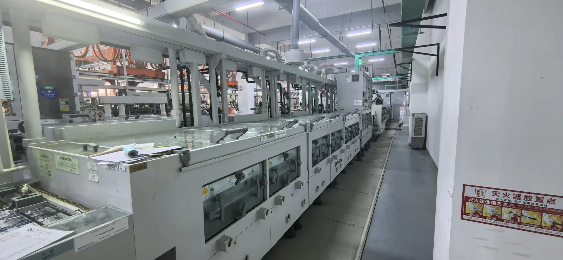

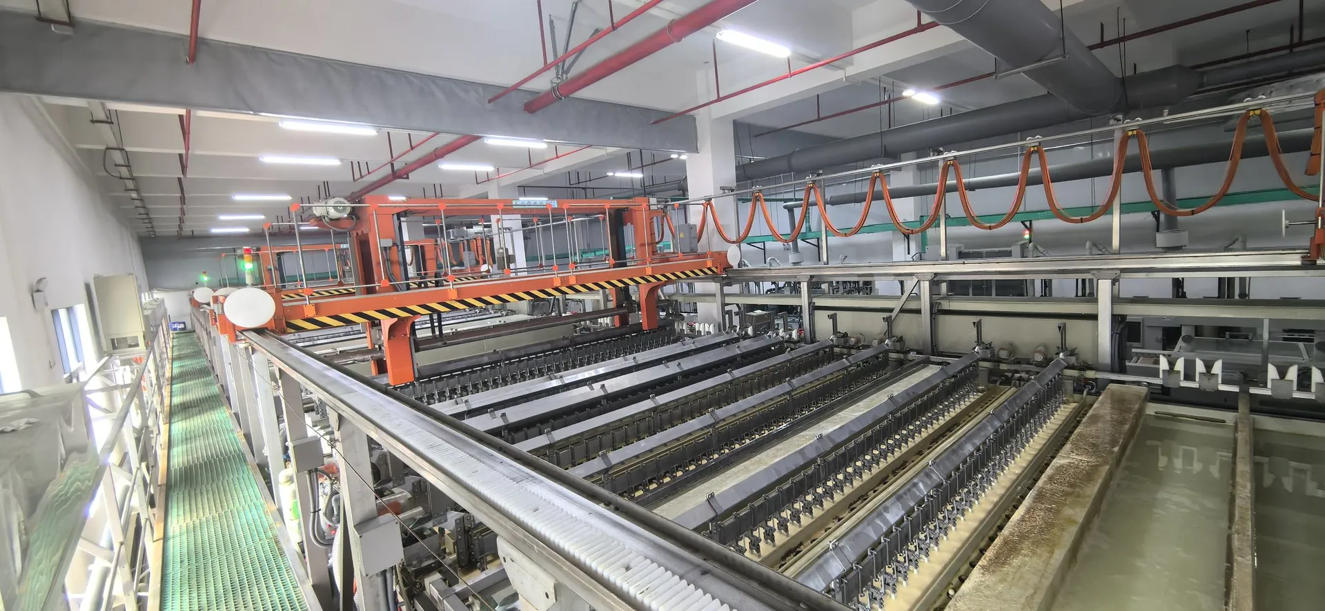
Leiterplattenfertigung und Prozessgrenzen
Erfahren Sie, wie starre und Starrflex-Leiterplatten entstehen und welche Mustergrenzen, Materialien und Prüfungen vor der Fertigung zu klären sind.
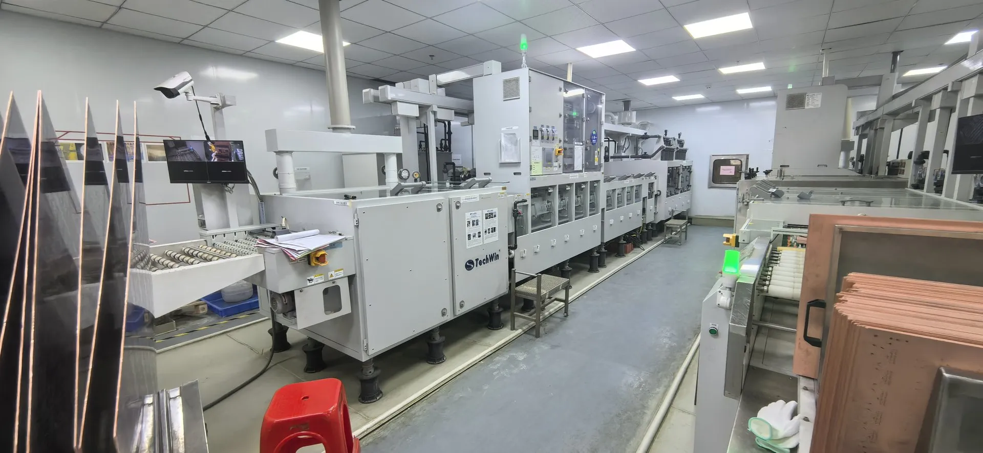
Werke und Fertigungsnetzwerk
Our Shenzhen team coordinates PCB production with the Meizhou partner site and other factories selected for the build. Production scope and qualifications are confirmed for the assigned site.
Fertigungspartner, Umfang der Autorisierung, Qualifikationen und Lieferumfang werden je Projekt bestätigt.
Herstellungsablauf für starre Leiterplatten
The process runs from laminate preparation through electrical test and final inspection.
Schneiden
Laminatplatten auf Arbeitsmaß zuschneiden.
Bildgebung der inneren Schicht
Innenschichtmuster abgebildet und geätzt, dann durch AOI überprüft.
Laminierung
Kerne und Prepregs in den Mehrschichtstapel eingepresst.
Bohren
Mechanisches und Laserbohren von Löchern und Durchkontaktierungen.
Beschichtung
Lochmetallisierung und Kupferbeschichtung.
Bildgebung der äußeren Schicht
Von AOI abgebildete, geätzte und geprüfte Außenschichtmuster.
Lötstopplack und Legende
Lötstopplack und Siebdruck aufgetragen.
Oberflächenbeschaffenheit
ENIG, Hartgold, Immersionszinn oder -silber, OSP und andere.
Profilerstellung
Fräsen, V-Schnitt und Konturbearbeitung.
Elektrischer Test und Endkontrolle
Flying-Probe- oder Vorrichtungstest, Endkontrolle und Verpackung.
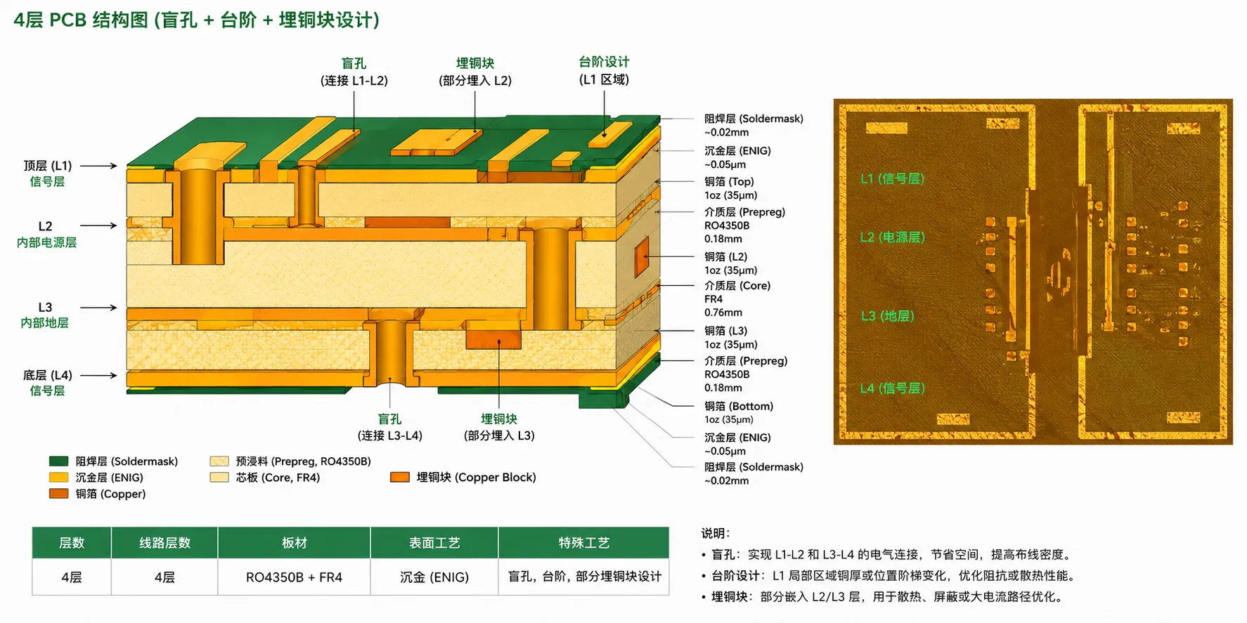
Rigid-flex boards bring two constructions together
The rigid-flex process prepares the FR-4 rigid section, flexible copper-clad laminate, coverlay and other lamination materials along separate paths. The flexible circuit is patterned and inspected before the coverlay is applied. The rigid and flexible sections are then combined in the specified order and laminated.
After lamination, the process uses X-ray for target location before subsequent drilling and profiling. The agreed construction determines where to remove material or control routing depth so the flexible section can be released. The board then goes through electrical test, final quality inspection and packing.
A rigid-flex drawing therefore needs more than an overall outline. It should show which layers continue through the flex region, where the coverlay and stiffeners sit, and the boundaries between rigid and flexible sections. These details affect both the build sequence and the points checked on the finished board.
What to confirm for each board family
Use the board family and production stage to identify what engineering needs to check.
| Board family | Engineering review points |
|---|---|
| Flexible Schaltkreise | Confirm the flex material, copper thickness, coverlay and stiffeners. |
| Conventional rigid boards | Check layer count, finished thickness, trace and space, copper weight, hole size and the required impedance tolerance against the intended construction. |
| Rigid-flex boards | Confirm the rigid and flexible layer arrangement and any air-gap, asymmetric or HDI structure. Review alignment, the coverlay and the flex release process together. |
| High-frequency and high-speed boards | Confirm the material system, hybrid lamination, hole geometry and impedance targets. |