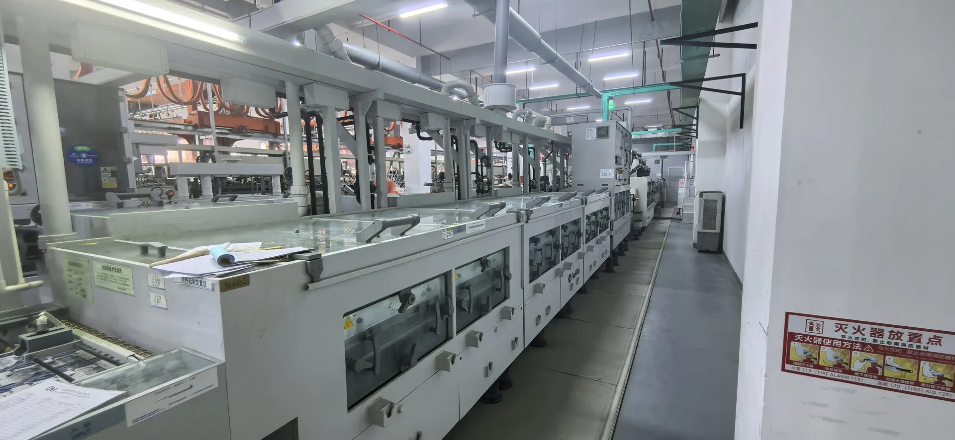


SMT Assembly for Fine-Pitch and BGA Boards
The standard SMT reference lists 0201 chips, IC lead pitch of at least 0.4 mm and BGA/CSP ball pitch of at least 0.5 mm. Finer packages need a separate review.

Highlight the component that drives the process
Mark 01005, very fine pitch, tall parts and parts sensitive to a second reflow. Provide the placement file, paste data and assembly drawing so side, rotation and stencil apertures can be checked together.
Agree on what inspection must show
AOI can check visible placement and joints. For hidden joints, specify the X-ray coverage and acceptance criteria you need. Provide separate instructions for programming or functional testing.
- Placement data and polarity
- Paste layer and stencil design
- Fine-pitch and BGA parts
- Inspection steps
SMT capability
| Specification | Standard process | Advanced / non-standard |
|---|---|---|
| Max component height | ≤ 6.5 mm | 6.5 mm < H ≤ 15 mm |
| Max component size | 200 × 125 mm | > 200 × 125 mm |
| Min chip size | 0201 (0.6 × 0.3 mm) | 01005 (0.4 × 0.2 mm) |
| Fine-pitch IC lead pitch | ≥ 0.4 mm | 0.3 mm < pitch < 0.4 mm |
| BGA / CSP ball pitch | ≥ 0.5 mm | 0.3 mm < pitch < 0.5 mm |
Advanced / non-standard processes are confirmed per project.
Typical applications
Control boards
Communication modules
Consumer electronics
What to send
Files for an assembly review
- BOM with manufacturer part numbers
- Placement (centroid) file
- Assembly drawing and polarity notes
- Gerber data including paste layers
- Test or programming instructions, if any
Start a project
Send your files and planned quantities. We will confirm the open engineering points before quoting.
SMT Assembly FAQs
Can you assemble both sides?
Double-sided assembly is reviewed per design.
Which inspections are used?
Inspection steps are agreed with the order during review.