
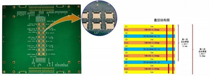
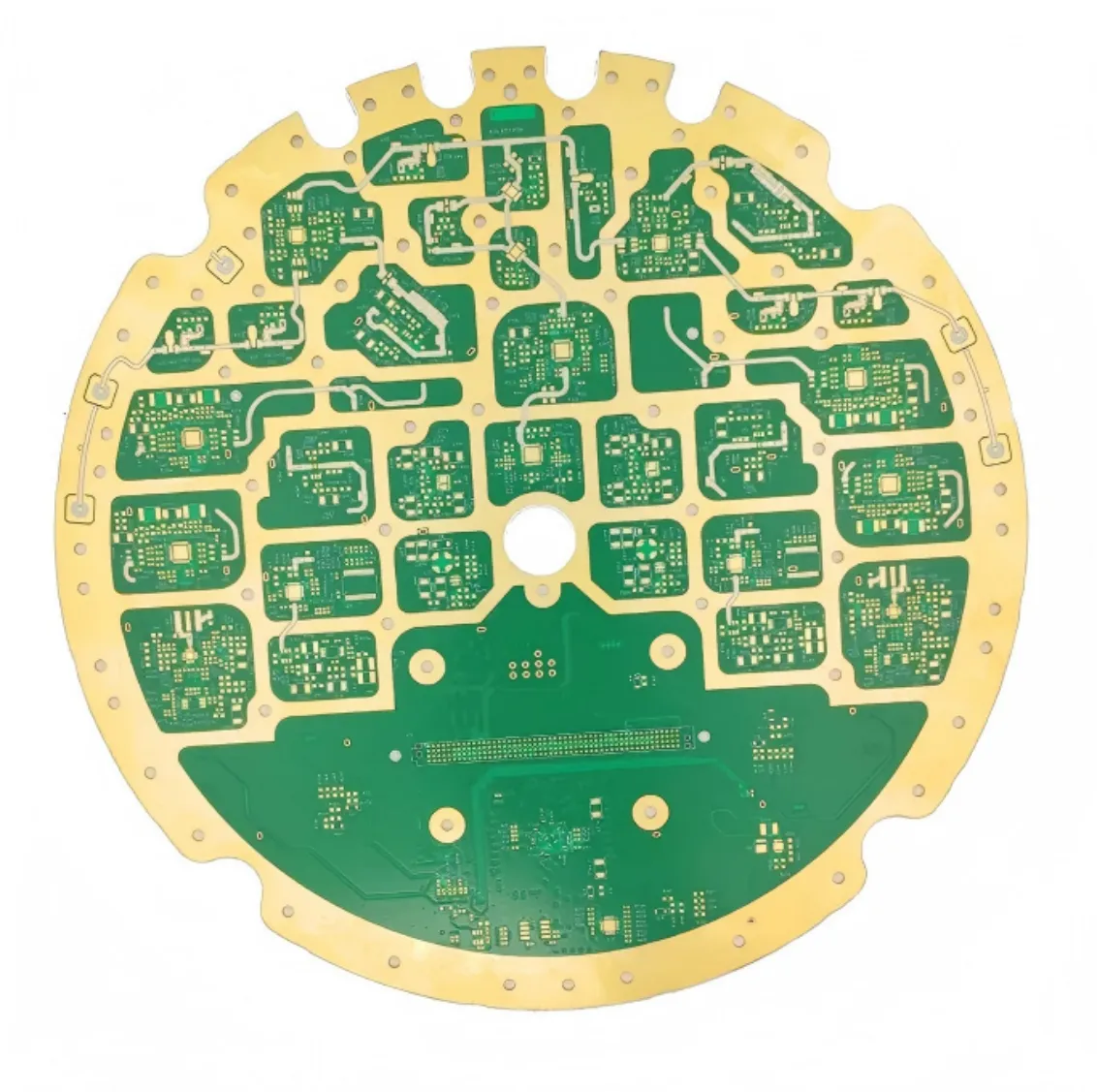
77 GHz radar high-frequency board
- Layers
- 18
- Materials
- TSM-DS3 + FR28 prepreg + S1000-2M, hybrid lamination
- Finish
- Immersion gold (ENIG)
- Special process
- Blind and buried vias, controlled impedance and 5 back-drill groups

Review low-loss laminates, reference planes, permitted via stubs and board thickness against the link budget.
The company sample uses Panasonic MEGTRON 8, a 3.1 mm finished thickness and 0.15 mm minimum hole. Blind vias and full-board electrolytic hard gold are part of the same construction.
Give data rates, loss targets, reference layers and impedance tolerances. For back-drilled connections, specify target layers, residual stubs and the verification method.
Typical requirements from the ShinePCB application capability sheet. Each project is reviewed against its own drawing and specification.
| End product / typical modules | Applicable PCB types | Key processes | Material direction | Engineering focus |
|---|---|---|---|---|
| AI servers / GPU accelerator cards / HPC — main board, switch board, high-speed interconnect, power | High-layer-count, backplane, HDI, high-speed, heavy copper | High layer count; back drilling; impedance; sequential lamination; POFV; heavy copper | MEGTRON 6/7/8, Tachyon 100G, TU-933 | 112G/224G insertion loss; registration; warpage; power delivery |
Application descriptions show typical board requirements. They are not customer references, and end-product standards remain the responsibility of the product owner. Signal-integrity and IPC class requirements follow the customer specification.
Compare stack-up, hole geometry and inspection requirements with your design.
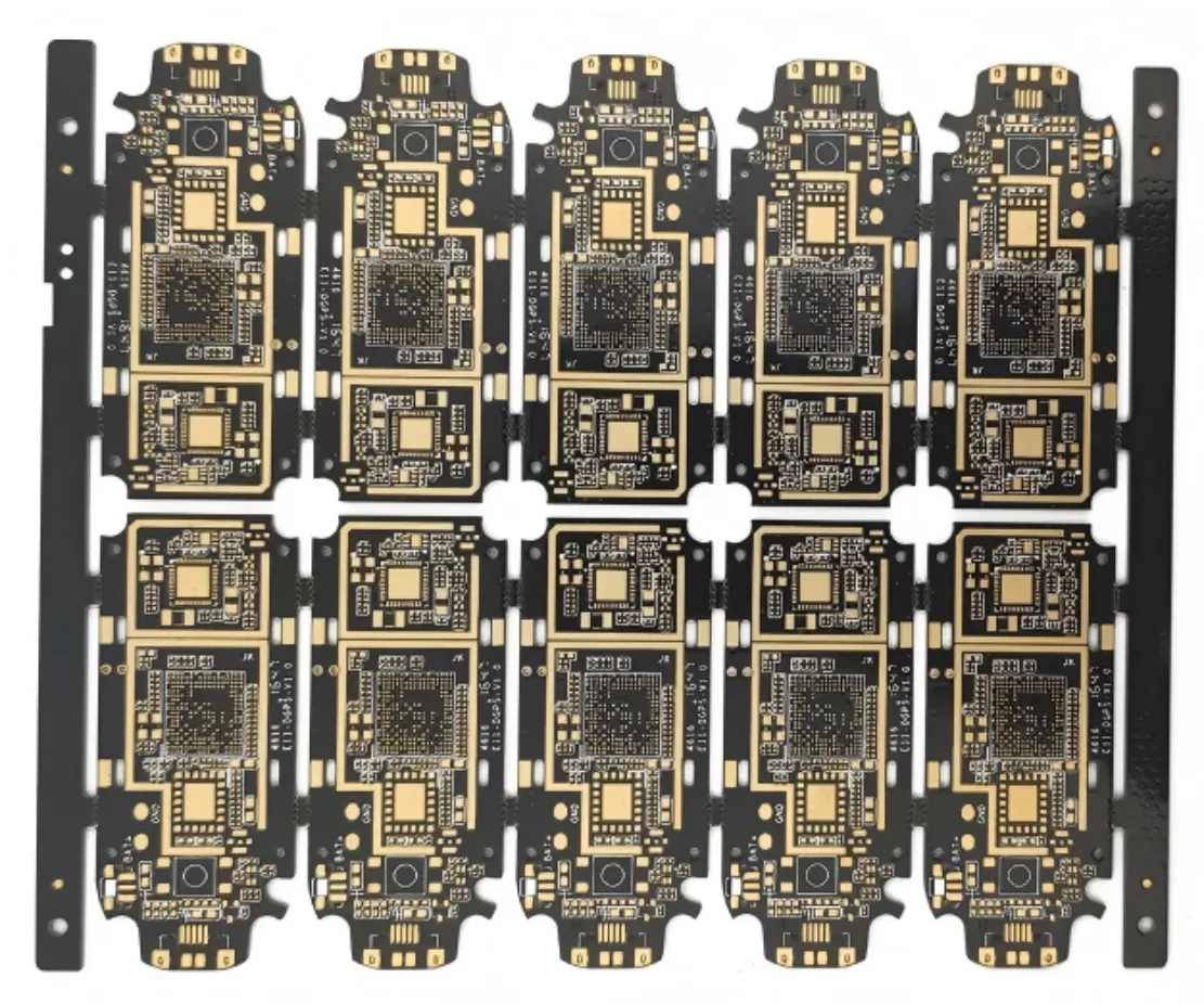
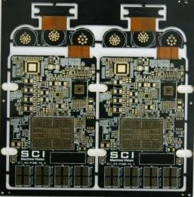
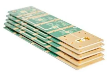
Layer count and construction are confirmed in engineering review.
Low-loss options are reviewed against your signal requirements.